Microsoft patents waveguide-based eye tracking technology for head mounted displays
4 min. read
Published on
Read our disclosure page to find out how can you help MSPoweruser sustain the editorial team Read more

To enable hands-free user interaction, a see-through, mixed reality display device system may be equipped with an eye tracking system. An easy way to implement eye tracking is to use a camera mounted on the frame of a head mounted display (HMD) device, wherein the camera is directly focused on the user’s eye. But such setup will cause at least partial obstruction of the see-through properties of the mixed reality display device system. Alternatively, a partial reflector may be used to fold the camera view path to the user’s temple. But this setup problematic if the eye tracking needs to work with prescription eyewear. Microsoft’s latest patent tries to solve this eye tracking problem using a transparent waveguide illuminated by infrared light.
Patent Summary:
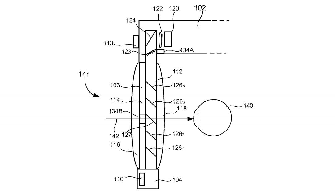
Certain embodiments described herein relate to a waveguide that is for use in tracking an eye that is illuminated by infrared light. Such a waveguide, which can be used in a head mounted display (HMD), but is not limited for use therewith, is transparent and includes an input-coupler and an output-coupler. The input-coupler comprises a grating area, formed by plurality of curved grating lines, that diffract light beams incident on the input-coupler into the waveguide and towards a common region at which is located the output-coupler. The curved grating lines of the input-coupler have a radially varying pitch. In accordance with an embodiment the radially varying pitch of the curved grating lines of the input-coupler decreases with increasing distance from the output-coupler. Preferably, the input-coupler and the output-coupler are positioned relative to one another to substantially achieve telecentricity. The output-coupler can comprise a linear grating, a holographic grating or a prism, but is not limited thereto.
When the input-coupler is positioned in front of an eye that is illuminated with infrared light, infrared light beams reflected from the eye and incident on the input-coupler enter the waveguide at the input-coupler, propagate through the waveguide from the input-coupler to the output-coupler by way of total internal reflections, and exit the waveguide proximate the output-coupler. The radially varying pitch of the curved grating lines of the input-coupler causes different beams of infrared light that are incident on respective different horizontal and vertical positions of the input-coupler to propagate through the waveguide at respective different angles of reflection and exit the waveguide at respective different angles of incidence relative to a surface of the waveguide through which the light beams exit.
The plurality of curved grating lines of the input-coupler each have a point of convergence that is located within the region of the waveguide at which is located the output-coupler. In a specific embodiment, the plurality of curved grating lines of the input-coupler are substantially concentric, each have substantially the same center of curvature, and each have substantially the same point of convergence. In an alternative embodiment, an optical transfer function of the input-coupler is substantially equivalent to an optical transfer function of an on-axis holographic lens combined with an optical transfer function of a linear diffraction grating. In this alternative embodiment, while the plurality of curved grating lines of the input-coupler are not substantially concentric, do not share substantially the same center of curvature, and do not share substantially the same point of convergence, the plurality of curved grating lines of the input-coupler will still each have a point of convergence that is located within the region of the waveguide at which is located the output-coupler.
In accordance with an embodiment, a system including an embodiment of the above summarized waveguide can also include an infrared illumination source that produces infrared light that is used to illuminate an eye. Such a system can also include a lens module that converts the infrared light beams that exit the waveguide from angularly encoded infrared light beams to two-dimensional spatially encoded infrared light beams. Additionally, such a system can include an sensor that produces eye tracking data in dependence on the two-dimensional spatially encoded infrared light beams produced using the lens module.
The current version of HoloLens does not support eye tracking, but we predict that the next version of HoloLens will include it. SensoMotoric Instruments is a leader in eye tracking technology for HMD devices. They are going to demonstrate their latest tech at CES next month. From their demo, we may get a glimpse of how eye tracking will work on HoloLens in the future.


User forum
0 messages